What You'll Need
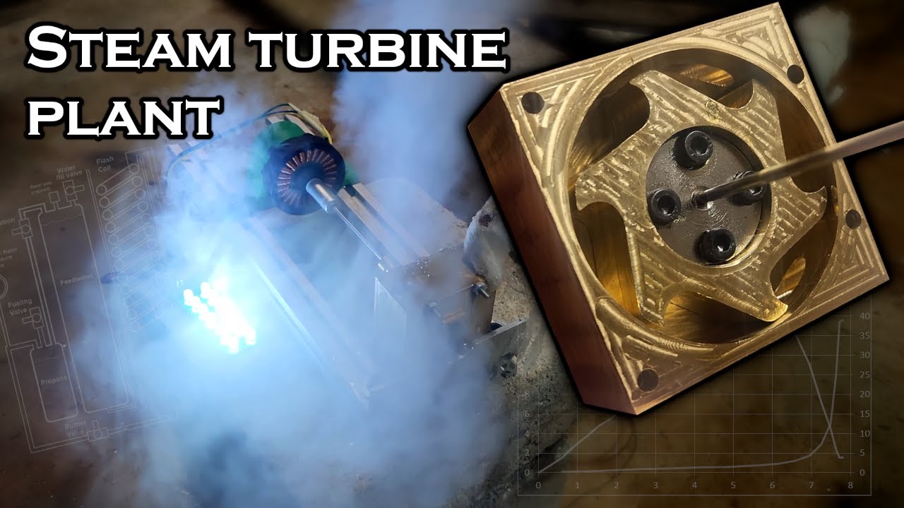
You're sick of paying for electricity, right? Me too. But this little steam-powered turbine won't make you energy independent. It will, however, make fire into electricity — inefficiently, but very cool. A few years back I built compressed air turbines with 3D-printed parts, and they worked okay. Then I thought: what if I ran one on steam? I dusted off my awful homemade CNC mill and figured I could machine a turbine out of metal instead of plastic.
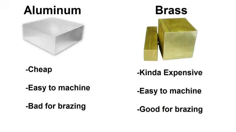
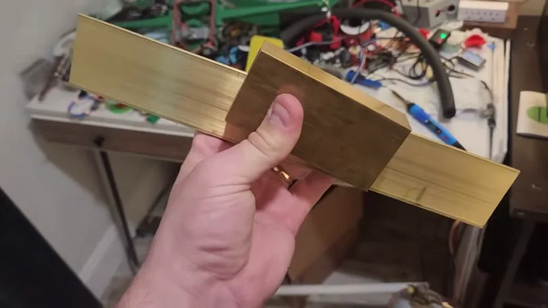
Brass machines nicely and you can braze copper fittings to it. I grabbed a 4x2x1-inch brass block for the rotor and housing, and a 2x8-inch sheet for the cover. Then I decided to try a flash boiler — no big tank you have to heat for hours. A flash boiler feeds pressurized water into a coil directly in the flame. Water boils instantly. The catch is you need to feed water at or above operating pressure. Usually you'd use a pump driven by the engine, but I wanted fewer moving parts. So I used a pressurized water tank with a tiny pinhole restriction. And since I’m using propane for heat, I figured I could just use the propane pressure to push the water — same pressure, double duty. It sounds nuts, but it worked.
Here's how I built it, step by step, with all the mistakes included.
Materials
- Brass block (2x2x1 inch for housing, 4x2x1 inch for rotor, 2x8x1/8 inch sheet for cap)
- 1/4-inch copper tubing for plumbing
- Copper ingot (or scrap) for nozzle
- 2mm steel shaft
- Shaft flange adapter (I got one from Amazon)
- Bearings for 2mm shaft (tiny ones)
- M3 bolts and nuts
- 1/4-inch flare fittings and nut
- Propane tank (15 lb for longer runs, small 1 lb for testing)
- Water tank (I used a 2.5-inch copper pipe, but PVC would work)
- Stainless steel pipe (for the flash boiler burner tube)
- Glass wool insulation
- Brushless motor with low KV rating (I used a 390KV motor)
- Schottky diodes (six, for three-phase rectifier)
- 220µF capacitor
- 2-ohm resistor and MOSFET (for variable load testing)
- Arduino or similar microcontroller (optional for power measurement)
- 20mm slotted rail and brackets
Tools
- CNC mill (or manual mill) capable of cutting brass
- 1/8-inch (3.17mm) two-flute endmill
- 1.5mm endmill for small holes
- Drill press
- Brazing torch and solder
- Propane torch for igniter
- Oscilloscope (helpful for tuning)
- Heat sink (large) for MOSFET
Step-by-Step Build
1. Mill the Housing
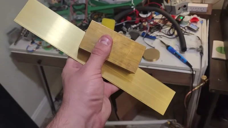
Start with the 2x2x1-inch brass block. Use a 1/8-inch endmill at 12,000 RPM, feed rate of 8 mm/s, 2 mm depth of cut, 70% stepover. Brass cuts super smooth — you can push harder than that. I didn’t even need cutting oil.
Cut the inside diameter of the housing to 46 mm diameter x 19 mm deep. Bore inlet and outlet holes tangent to the rotor — 1/4-inch diameter, about 5mm from the housing centerline. Drill bolt holes for the bearing block (14 mm apart, M3 thread). I used a 1.5mm endmill to cut small holes instead of drilling — gives cleaner results. If the endmill can't go deep enough, finish with a drill press.
Flip the housing over and cut a pocket for the 2mm shaft bearing. On the side, mill the inlet and outlet ports. I made one mistake: I forgot to raise the endmill before moving it manually after cutting the bolt holes. That gouge got covered by the cap, so no big deal. Not perfect, but for a first brass piece on a 3D-printed CNC router, I’m happy.
2. Cut the Cap
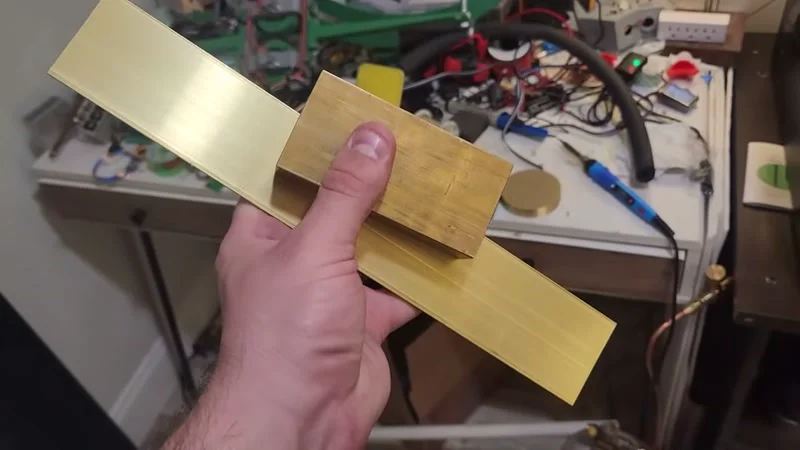
From the brass sheet, cut a cover plate to close the housing. It just needs to fit flush with the housing face and include screw holes matching the mounting pattern.
3. Machine the Rotor
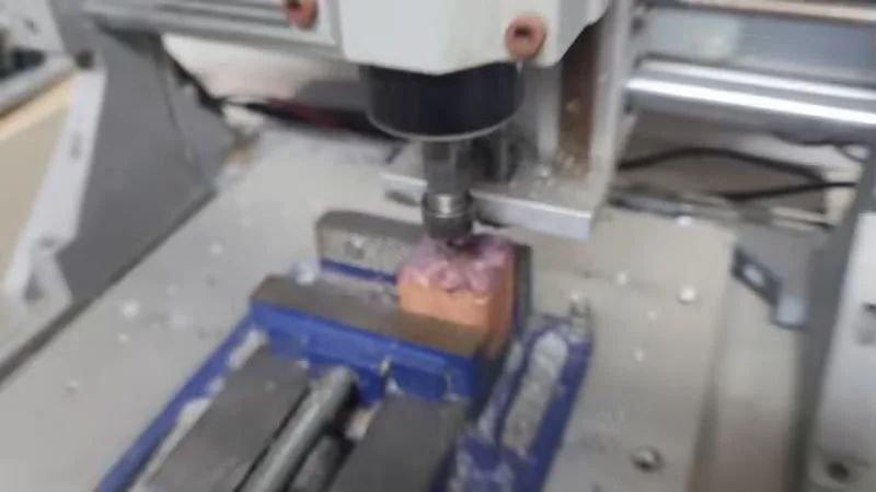
Start with the recess for the shaft adapter. It needs to be deep enough so the flange and screw heads sit flush with the rotor face. Then cut the outer profile. I cut a single slot all the way around — I know that’s bad practice (stress concentration?), but I got away with it. The slot depth is only down to the rotor thickness (18 mm). But the brass stock is 1 inch (25.4 mm). So flip it over and mill away the remaining material until the rotor falls out.
When the endmill first hit the slot from the other side, I saw the outline appearing unevenly — the block wasn’t perfectly level. No big deal, just keep cutting.
Finish the rotor. Then mount the shaft adapter with four M3 bolts into tapped holes in the rotor. I installed a 2mm shaft into the adapter.
4. Balance the Rotor (This Took Forever)
The rotor was horribly imbalanced because I lost zero position halfway through cutting and had to re-zero by eye. I drilled hole after hole into the rotor until it spun smoothly — a Swiss-cheese mess, but after half an hour it ran true.
5. Make the Nozzle
Ideally you’d use a converging-diverging nozzle to maximize conversion of pressure energy to kinetic energy. But machining one that tiny is way beyond my skill. I went with a simple hole: a 1mm orifice in a copper tube. I cut a piece from copper ingot I’d melted in a previous video, drilled a 1mm hole, and brazed it into a standard 1/4-inch copper tube.
6. Cut Bearing Cover Plates
Cut two small plates to hold the shaft bearings in place. Thread the inlet port for a set screw to hold the nozzle tube.
7. Assemble the Turbine
Put it all together: rotor inside housing, bearings in place, cap on, nozzle tube secured. The nozzle tube has a 1/4-inch flare nut to connect to a flare fitting. I hooked it up to my air compressor for a quick test. At 20 psi it spun up fine, but I dropped the assembly and bent the shaft — that caused vibration. Still, it kept spinning even when I squeezed the shaft (trying to stop it). Good sign.
8. Build the Generator and Test Setup

Mount the turbine to 20mm slotted rail using an aluminum L-bracket. Couple the shaft to a small brushless motor (390KV) with a long shaft and coupler — the long shaft acts as a heat brake so the motor stays near room temperature.
For the first test with a small brushed DC motor, I got only 1.7-1.8V open circuit. That motor is rated 6,000 RPM at 3V, so it was only spinning 3,400-3,600 RPM. Not great.
Switched to the brushless motor. At 100 psi from the air tank, voltage between two phases showed 7.3V peak. Frequency read about 1 kHz, which with 18-20 poles means actual RPM around 3,200-3,600 — matches earlier. The brushless motor is much more efficient (80-90% vs 40-50% for brushed).
9. Build a Three-Phase Rectifier
Regular bridge rectifier won't work for three-phase AC. You need six diodes in a three-phase rectifier. Use Schottky diodes — voltage drop is only ~0.3V per diode, so total drop ~0.6V per phase instead of 1.2-1.4V. That matters when your voltages are only 5-10V.
I wired six Schottky diodes on a small board, added a 220µF capacitor across the output, and boom — clean DC.
10. Test Power Output with Variable Load
To measure power, I built a quick variable load: a 2-ohm resistor in series with a MOSFET. By adjusting the gate voltage (0-5V), the MOSFET acts like a variable resistor in the linear region. Measure voltage across the resistor (high side to low side) to get current, and voltage from generator to ground for voltage. An Arduino reads the analog values, computes power, and sends them to a laptop.
The MOSFET and resistor sit on a huge heat sink. Looks goofy but works perfectly.
11. Build the Flash Boiler
For the pressurized water tank, I used a big 2.5-inch copper pipe leftover from a cryocooler project. PVC would have been fine, but I had this. Fill water through a valve with a funnel.
For the flash boiler: coil a few feet of 1/4-inch copper tubing inside a stainless steel pipe. The propane fuel feeds through a capillary tube (0.6mm inner diameter — I started at 1mm, that was way too much and turned the pipe red hot). The propane jet creates a Venturi effect, drawing air into the pipe for combustion. The coil starts about a third of the way up the pipe so the propane/air mix has room to burn before hitting the coil.
Safety: Always light the igniter torch before opening the fuel valve. If the pipe floods with propane, it'll backfire and scare the hell out of you.
Open the water valve. Within seconds, steam comes out of the nozzle. The 1 lb propane bottle froze after a couple of minutes, dropping pressure from 120 psi to 60 psi. For real runs, connect to a 15 lb tank.
12. Run the Turbine on Steam
Hook the boiler output to the turbine nozzle. Use glass wool insulation on the steam line to keep heat in. Fire it up — 12 seconds from cold start to lighting LEDs. That’s the beauty of flash steam: no waiting.
Steam exhaust fans out at an angle — that means a lot of pressure energy is wasted because the nozzle isn't converging-diverging and the turbine clearances are too loose.
13. Measure Real Power
After 10 minutes of running at ~60 psi steam pressure, I collected data with the variable load. Open circuit voltage: just under 8V. As load increases, current caps around 3A. Power peaks at 17 watts at 5.1V with a load resistance of about 1.9 ohms. Enough to charge a phone via a 5V buck converter.
Efficiency? Rough calculation: 1 gram per second of water fed in, 2600 J/g to boil from room temp — that's 2600 watts of heat absorbed by the coil. Turbine output 17W, so about 0.65% efficiency. Yikes. But a lot of heat is lost to the surroundings despite the insulation, so real efficiency is even lower. The big losses are loose machining tolerances and no converging-diverging nozzle. A low-speed reciprocating piston engine might be better for torque and expansion ratio.
What I’d Do Differently
- Tighter rotor clearances (0.5mm is too much — go for 0.1-0.2mm if you can)
- Proper converging-diverging nozzle
- Use a regulator on the propane for steady pressure
- Maybe try a sliding vane turbine — those might hold up at steam temperatures with the right material
- Use a larger propane tank to maintain pressure
Final Thoughts
This micro steam plant does turn fire into electricity. Seventeen watts isn't much, but it charges a phone and runs some LEDs. It looks awesome when it's running. Just don't expect to ditch the grid for it. For now, it's a cool bench project — and a reminder that machining your own parts from solid brass feels really satisfying.